
UNITED REPUBLIC OF KIVU
Methane Gas from Kivu
Kivu Lake in the United Rerpublic
of Kivu contains an enormous quantity of dissolved methane. Exploiting this
methane is a fabulous opportunity for the economic development.
This gas also constitutes a risk of cataclysmic explosion, as occurred in
Cameroon at Nyos Lake.
A scientific French and Swiss group studied the physicochemical characteristics
of the lake and evaluated the risk of a gas explosion.
The Company Data Environnement has set up a pilot station to extract the methane
for energetic purposes and proposed the promotion of this gas for diverse
applications.
Lake Kivu has recently been found to contain approximately 55 billion cubic metres of dissolved methane gas at a depth of 300 metres. Extraction of the gas is currently being done on a small scale, with the extracted gas being used to run boilers at a brewery. As far as large-scale exploitation of this resource is concerned, the Rwandan government has signed an $80 million deal with an international consortium to produce methane from the lake. Extraction is said to be extremely cost effective and simple because once the gas rich water is pumped up the dissolved gases (primarily carbon dioxide, hydrogen sulphide and methane) begin to bubble out as the water pressure gets lower. This project is expected to increase Rwanda's energy generation capability by as much as 20 times and will enable Rwanda to sell electricity to neighboring African countries.
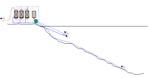
KIVU METHANE GAS EXTRACTION
Lake Kivu is unique : its deep
waters contain an enormous quantity of dissolved gas. There are, in fact,
65 billion cubic metres of methane, in other words the equivalent of 50 million
tonnes of petrol (tep) lying at the bottom of the lake under 250 m of water.
If it were exploited, this energy, veritable manna from heaven, would provide
Rwanda with an almost inexhaustible source of energy, freeing it from worry
about energy needs linked to its development projects.
The Data Environment company has developed a pilot station for the extraction of methane for energy purposes and proposes various applications for this gas.
THE EX-SOLUTION AND AUTO-SIPHON PHENOMENON
Ex-solution is the phenomenon of the formation of gas bubbles in a liquid which has become saturated. The saturation limit of a gas in a liquid depends on two factors: the total quantity of dissolved gas and the pressure of the liquid (that is to say the depth, in the case of a lake).
The formation of bubbles can take place either by increasing the quantity of dissolved gas or by diminishing the pressure (that is to say, depth). If one of these conditions is fulfilled, and if the level of saturation is reached, tiny bubbles of gas form in the water which then rise to the surface. These little bubbles carry with them liquid already saturated in gas. New bubbles appear in this liquid. On their way up, the size of the bubbles increases. A chain reaction is set in motion. The ex-solution, once begun, will rapidly develop in an 'avalanche' process.
If the phenomenon is not controlled, a veritable explosion of a mixture of water and gas will occur at the surface. This is precisely the phenomenon which can be observed on opening a bottle of champagne or of lemonade : by lowering the pressure inside the bottle, bubbles of dissolved gas form suddenly and, taking liquid with them, rise to the surface.
On a huge scale, this is also the phenomenon which produced the catastrophe of Lake Nyos (Cameroon) on the night of the 21st August, 1986. The saturation limit was surpassed in the deep waters of the lake, the ex-solution process was triggered off and developed in all the lake waters in a chain reaction. A gas explosion threw up a column of water over 80 m high. There was a violent overturning of all the lake water. Following this, the enormous quantity of carbonic gas thus liberated, being denser than air, 'flowed' through the neighbouring valleys, suffocating all forms of life as far as 30 kms from the lake. I800 people thus perished because of this catastrophe.
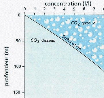
CO2 saturation and degassing limit

Auto-siphoning at work
at Lake Kivu
WORKING PRINCIPLE OF THE PILOT STATION
Our project proposes the immersion of the entire
system (separator and washing column) at a shallow depth.
the fact of working entirely under water has numerous advantages :
the volume of gas freed by the separator and
needing to be washed decreases the pressure of the gas rises, so the transport
by gas pipeline to the shore is made easier washing and transport operations
can be achieved with a minimum of energy from the exterior
the richness in methane of the gas mixture is directly optimised at the separator
the efficacity of putting the CO2 into solution in the washing column is increased.
But this option has also some negative aspects:
the driving force of the autosiphon is diminished
part of the methane stays in solution in the discharged water and is thus
unexploited.
These remarks are of major importance since they illustrate the compromise
to be made between total gas flow and loss of methane.
Degassing below the surface of the lake
Methane being 25 times less soluble in water than carbon dioxide, its ex-solution should occur before that of CO2. In fact, if the two gases behave independently of each other, the first bubbles of methane should appear at a depth of about 120m whereas those of carbon dioxide should form only at about a depth of 15 metres.
Apparently, by positioning the separator at this depth, one should obtain pure methane, the carbon dioxide staying dissolved in the water. This theoretical shortcut is obviously wrong, since it does not take into account the establishment of a balance between chemical types : when a bubble forms, all of the dissolved gas spreads in the bubble until a balance of partial pressures with the water is obtained. The moment a bubble of methane appears, the instability thus created transforms the other dissolved elements into gas until the balance of partial pressures is achieved both inside the bubble and in the liquid.
This important observation is nevertheless difficult to quantify precisely: the calculation of the behaviour of diphasic fluid moving in a degassing column is in fact difficult to make, given the great number of parameters which come into play. It is, however, recognised that in proceeding with the separation of gas and liquid under pressure, that is to say submerging the separator at a certain depth, the richness of the methane in the mixture will be clearly greater than that obtained with a separator on the surface. The conclusions of the majority of projects during the past thirty years point in that direction.
On the other hand, from the fact that a large percentage of the carbon dioxide stays in solution when you operate at depth, it follows that the volume of gas needing treatment is smaller. Successive washing operations can thus be recalculated in order to obtain a gas even richer in methane. Unfortunately there are two negative points to consider.
Firstly, as the volume of gas resulting from
the ex-solution is less, the driving force of the auto-pumping is equally
diminished.
Secondly, the separation of liquid and gas at depth increases the quantity
of methane remaining in solution in the water, giving rise to a loss in the
total quantity of potentially recuperable methane.
Methane loss, gas flow and criteria for chosing energy
The diminution of gas flow by volume according to the increase in the depth of the separator is of major importance in the overall concept of the system. In fact the efficacity of the washing and its cost in energy depends directly on the volume of gas to be treated. By decreasing this quantity of gas, the quantity of washing water needed is decreased similarly, this leading to a gain in the dimensions of the washing column.
To minimize the quantities of gas to be washed it seems that a minimum depth of 10 m is necessary. But the deeper the separation of gas and liquid takes place, the more methane, which remains in solution, is lost. The depth will thus largely be limited by this phenomenon of the non-ex-solution of methane. For the loss to be minimised, it seems that a maximum of 30 m would represent the limit of exploitation.
It is interesting to evaluate the variations in energy production of the system according to the depth of installation of the separator. This criteria clearly shows the need not to try to work too deeply. In fact a calculation based on gas and liquid flow allows an estimation of 13% potential energy loss for an increase in depth of 5 m.
If the extraction and washing of the gas under the lake surface seems the best solution, it would nevertheless be wise not to exagerate the benefits of such a method. Losses in extractible methane are such that energy production is seriously penalised.
COMPARISON OF DIFFERENT METHODS ENVISAGED
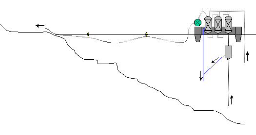
These projects gather together all of the possibilities for the installation of a energy harnessing station. From reading these reports one can extract three really distinct options : the on-shore variation (on the lake shore), the semi-off-shore variation (extraction system on barge and treatment on-shore) and the off-shore variation.
Off-shore (extraction and treatment on barge)
Separator under the lake surface
Advantages
Open choice of site on the lake. Maximum reduction in all piping.
Number of extraction installations a priori unlimited. Mobility of harnessing
stations. Preservation of extraction columns due to the lack of friction on
lake bottom. Less loss of capacity and less risk of blocking because of the
vertical nature of the columns. Increased yield due to the separator being
at depth
Disadvantages
Added investment for the design and manufacture of the barge. Transport of
workers and maintenance material by boat. Presence of a purified gas pipeline
under the lake surface. (*) Note : in the hypothesis that the separator is
on the barge the yield will be equivalent to the on-shore solution and the
main advantage of the off-shore solution would be lost.
Semi-off-shore (extraction system on barge and treatment on shore)
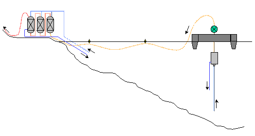
Separator under the lake surface
Advantages
Preservation of extraction columns due to the lack of friction on lake bottom.
Less loss of capacity and less risk of blocking because of the vertical nature
of the columns
Increased yield due to the separator being at depth.
Disadvantages
Presence of an unrefined gas pipeline under the lake surface
Separation of the station into two distinct units resulting in the doubling
of security, service and maintenance personnel. Choice of lake site dependent
on where treatment plant could be established on the shore. (*) Note : in
the hypothesis that the separator is on the barge the yield will be equivalent
to the on-shore solution and the main advantage of the off-shore solution
would be lost
On-shore (extraction and treatment system on the lake shore)
Seperator below lake surface
Advantages
Pressure equivalent to immersed solution
Disadvantages
Prohibitive cost of the trench protecting the
entire installation. Scarcity of sites likely to comply with the requirement
of such a solution
Separator above the lake surface
Advantages
Disadvantages
Low pressure in the separator a large amount of gas to be processed proliferation
of machinery/equipment
Energy cost of the extra maintenance
Note : taken together, the inconveniences of this solution mean that, unless
one accepts a backward step, one cannot rationally consider an entirely on-shore
solution for the installation, (as is currently the case at Cape Rubona).
Advantages and disadvantages common to the 2 positions of the on-shore separator:
Advantages
Ease of access for subsequent work,
Ease of access for personnel,
No sunken cables
Disadvantages
Lengthening of the harnessing and suppression
columns,
Serious charge loss due to the profile of lake bed,
Scarcity of sites with sufficiently sloping sides.
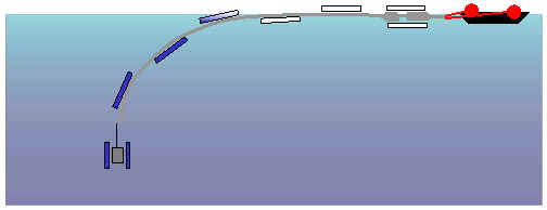
DIAGRAMM OF THE ENTIRE EXTRACTION PLANT
The technological choice selected is that of
off-shore extraction with transportation of the methane to the shore by gas
pipeline from the barge.
This installation has a number of advantages over the on-shore solution currently
used at Cape Rubona :
The vertical position of the column will favour a homogenous flow of diphasic liquid by avoiding systematic blockages. In addition, in a vertical position the total length of the column will be reduced from the present 850 m to 330-340 m, which will reduce charge loss and the cost of equipment.
The suspended column will not be subjected to scraping due to movement of the lake any more and can be easily hoisted to the surface for adjustment or repair.
Of course maintenance is more difficult on a floating structure and the construction of a barge able to carry all the installations involves a not inconsiderable increase in costs. But in spite of this, at the present moment the off-shore solution seems to offer the best compromise for the extraction of gas.
The installation which we are suggesting is thus made up of an off-shore extraction barge supporting the entire separation and washing equipment. Recuperated gas is then carried by submerged gas pipeline to the consumption unit on shore.
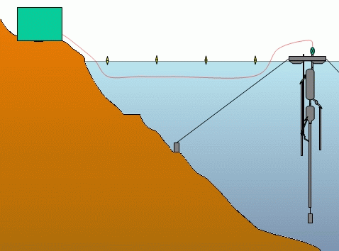
Diagram of the entire extraction
plant
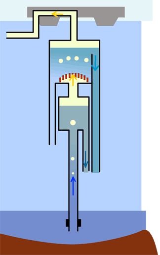
DESCRIPTION OF THE COLUMN
The diagram opposite shows the gas extraction column. It is made up of 330 m of PEHD polyethylene tubes under the separator. A flow regulator for the column is placed at a depth of 100 m. The column is then attached to the base of the first unit, the separator.
The gas lift is connected 20 metres below the separator on the main column, that is to say at a total depth of about 40 m. The supply pipe for the gas lift is a narrow gauge PE tube.
The separator is a metal cylinder inside which the gas is separated from the water . Two outlets are joined to the separator, one to return the water to the depths (below), the other for the untreated gas (above).
The water outlet rejoins the column of waste washing water, whereas the the gas outlet directly rejoins the second unit, the washing column.
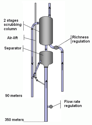
Diagram of an extraction column
Flow inside the column
The figure opposite illustrates the circulation of different liquids in the system during the process of separation and washing of gas.
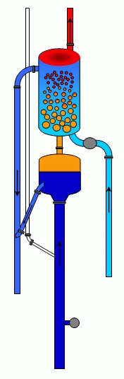
Diagram of movement of liquid in the system
WASHING
Preferential dissolution washing columns function according to a simple principle of physics which takes into account the different solubiities of gases in a liquid. Very roughly speaking, since CO2 is 25 times more soluble than methane, it will dissolve 25 times more easily in contact with water.
Washing thus consists in passing
the mixture of gas to be purified through a current of pure water. In order
to optimise gas-liquid exchange there must be sufficient gas in the liquid
: the gas enters, either through a perforated plate, or through a lining which
favourises the formation of innumerable tiny bubbles, thus increasing the
surface area for the gas-liquid exchange. Since CO2 has a higher solubility
than CH4, it will dissolve preferentially and thus the proportion of methane
will increase.
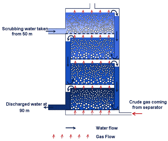
Principle of a four storey washing column with perforated plates
Our experimental modelling has shown the pointlessness of extreme washing of the methane gas. In fact, during the washing process the CO2 solublises. This process increases the concentration of methane gas extracted.
As during the separation process, the phenomena of the dissolution of the different gases are not independent. The CO2 does not first completely enter into solution before the methane. The two events are simultaneous, the difference in solubility of these two gases means only that the CO2 is dissolved preferentially.
For a methane-rich gas the washing procedure will have this unwanted effect: the higher the concentration in methane the more will be put into solution - a scaling factor to be taken into account. Even if methane is 25 times less soluble than CO2, to enrich the gas to over 85% methane would result in to large a loss of that methane. Taking into account the relatively small loss of calorific power between pure methane and a gas with 85% methane there is no justification for wanting to enrich the gas above this latter level and in so doing wasting methane in the lake water.
Different solutions have been considered for washing the gas. It has been decided to adopt the choices made for the Cape Rubona plant, except that the washing columns will be submerged. Washing will be done using running water, gas passing through a metal grid in order to obtain a fine dispersion of the gas which would favour the solublisation of the CO2. Columns with lining, like Raschig rings or Pale rings, were excluded, they being incompatible with the size of the equipment.
COMMAND AND CONTROL SYSTEM OF THE COLUMN
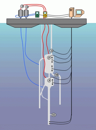

Diagram of the entire command
and control system of the column.
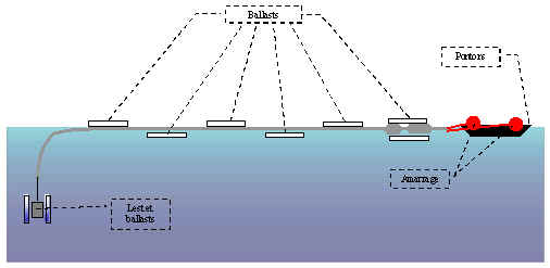
DEPLOYMENT OF THE COLUMN
The column will be assembled on
the ground. As it is lengthened it will be pulled into the lake. Once all
the pieces are assembled the column will be towed out into the lake by boat
and fixed to the barge, which has previously been anchored.
The following diagrams show the different phases of the immersion of the column
using ballast linked in series to a compressor.
First phase in the immersion
of the column.
The ballast for the column begins to fill with water. The filling process
for the ballast is slow and reversible if there is a problem during the immersion
of the column.
Intermediate phase in
the immersion of the column.
The ballast containers are filled one after the other so that the speed of
descent of the column is controlled.
Final deployment of the
column.
All the ballast containers are full and the ballast of the column keeps this
latter vertical. The dimensions of the column ballast depend on the force
of expulsion developed by the auto-siphon. Experimental models having determined
this force, the ballast will be larger than strictly necessary so as to avoid
any pointless risk.
It was decided to leave the column with a certain degree of free play by not making the ballast containers rest on the lake bottom. In fact, although the column is ballasted it can follow the movements of the barge caused, for example, by currents. This degree of freedom seems to us to be indispensible given the fact that pressures caused by wind and swell on the lake can be significant.

OBJECTIVES AND PRODUCTIVITY
Our project proposes set up a methane gas extraction plant which will provide
a local response to energy needs. A number of industrial sized modules could
be installed on the lake at various sites of potential consumption. This choice
of delocalised sites seems a better solution than the setting up of a single
production centre.
This approach is more in line
with official wishes for development and the regrouping of local populations.
Providing energy in certain specific places would aid this regrouping for
the local development of artisanal or even industrial projects
We have scaled our pilot extraction plant to produce 2.5 million Nm3 per year,
which is to say between 5 and 10 times less than the large scale projects
envisaged in the past. These production units can of course be replicated
in order to supply enough gas to the different large consumers of calorific
energy. In order to best respond to the specific needs of the different conceivable
projects, we are also proposing two other types of extraction plant, identical
in working principle but whose flow and equipment have been redimensioned
according to the quantity of energy to be extracted.
The different kinds of consumption conceivable for methane gas
|
Consumption |
Type of project |
Treatment and transfer unit |
|
Calorific energy for large-scale consumer |
Industries
like:
|
Transfer by gas pipeline or by compressed-gas lorry |
|
Calorific energy for small-scale consumer
Lower
production
|
Industries
like :
Domestic use |
|
|
Electrical energy Higher production option |
Integration in the National Grid
Electrification
of villages
|
Power station and electricity grid |
EUROPEAN UNION CONTRACT
RESULTS OF THE EXPERIMENTAL CAMPAIGN OF NOVEMBER 2002
Contract holder : 'Data Environnement' Company, F-73000 Chambéry le Haut.
In order to confirm the working hypotheses provided by our computer generated calculations of diphasic flow in the case of a mixture of carbon and methane gas, an experimental field trip took place from mid-November to mid-December on Lake Kiva.
Two important results were highlighted by the experiments made during this trip :
Firstly, all flow measurements confirm the validity of the computer generated calculations of diphasic flow. This confirmation allows for the extrapolation of the calculations to an industrial usage many times greater than what was achieved here.
Secondly, the (unexpected) discovery of an
enrichment in methane according to depth, which clearly parts company from
the law forcast by models of equilibrium, has important consequences for the
design of future systems of methane extraction.
The fact that the gas escaping from the separator has a lower methane content
than expected implies that the water expelled by the separator contains more
methane than was foreseen. The loss of water in the discharged water (from
the separator and from the washing column) becomes the main problem to deal
with in order to optimise the design of the equipment. This fact argues in
favour of positioning the separator at a shallow depth. A depth of 30 m seems
too much, given the loss of methane produced; the optimal depth foreseeable
is thus 25 m, maybe even 20 m.

PUTTING THE METHANE GAS TO WORK
65 billion m3 of usable methane are lying dormant at the bottom of Lake Kivu, at a depth of 250 m.
This manna from heaven, if exploited, will give Rwanda an energy source commensurate with its development projects.
Distributed by gas pipeline or compressed and then transported by road it could supply the country's industries: cementworks, tea-drying plant, brewery etc.
Used by gas driven engines with alternators, this methane will play a role in suppling the country's electricity.
The fight against deforestation is another major point in favour of the exploitation of Lake Kivu's methane.

Horizontal distribution of methane in economically exploitable concentrations in the main basin of Lake Kivu. Only the 280 m and 340 m isobaths are shown.
EVALUATION OF METHANE GAS DEPOSIT
Using a bathymetric chart established by Lahmeyer and Osae in 1998 we have added the depth contours 280 m (in red) and 340 m (in yellow).
This diagram facilitates the estimation of the productive horizontal surface of the lake, depending on the depth at which extraction takes place. It also allows for the rapid targetting of favourable sites for setting up methane extraction plants after examining the distance between productive layers and the shore.
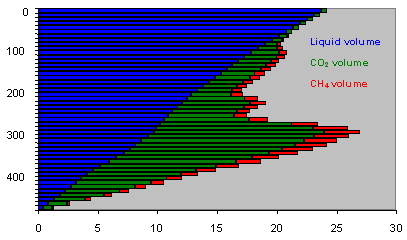
We have measured the respective volumes of water, CO2 and CH4 in layers 10 m thick.
Notice on this diagram the clear distinction
between the lake water above 260 m in depth (weak in dissolved gas) and that
below 260 m which contains a high proportion of dissolved gas. Only the methane-rich
layers below this depth contour can be considered economically viable.
First of all, look at some quantative measurements extrapolated from this
diagram :
total volume of lake 560 km3
total volume (TPN° of dissolved CO2 : 255 km3
total volume of dissolved CH4 : 65km3.
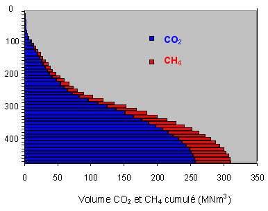
Cumulative presentation of carbon dioxide and methane according to depth.
We make a distinction between the quantity of methane dissolved and the quantity of methane extractible (net result at outlet of exploitation plant). We estimate in fact, following our calculations, that about 20% of the methane will be discharged (lost) to the deep waters of the lake during the separation and washing stages. Note that all these figures are given in volumes of pure methane TPN (1 bar pressure, temperature 0°C°.
Schematically we can divide the lake into four layers, of which three contain methane which can be considered economically exploitable. These three layers should be considered in terms of difficulty, because of depth (distance from the shore) in setting up extraction columns.
Extraction at a depth of 300 m
(260 - 300m layer : zone 1)
Volume of dissolved methane : 13.3 km3,
volume of extractible methane : 10.6 km3..
Extraction at a depth of 350 m
(300 - 350m layer : zone 2)
Volume of dissolved methane : 15 km3,
volume of extractible methane : 12.3 km3.
Extraction at the deepest part of the lake
(350 - 485m layer : zone 3)
Volume of dissolved methane : 14.9 km3,
volume of extractible methane : 11.9 km3.
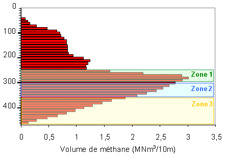
Vertical distribution of volume of methane in 10 m layers : economically interesting exploitable zones are shown in transluscent form. This diagram allows for an estimation of the quantity of economically exploitable gas, using the criteria of richness in gas and distance from shore.
To conclude, of the 65km3 of gas dissolved
in the lake :
28.3 km3 are easy to exploit and would give 22.6 km3 of pure methane TPN,
15 km3 are accessible with more difficulty and would provide 12 m3 of pure
methane TPN. 17 km3 are to eb considered as not economically viable.
Total volume of extractible methane : 34.5 km3.
It is important to optimise the exploitation system so as to minimise the quantity of methane discharged in deep water during the separation and washing stages. We think we can limit this loss of methane to between 20% and 25%. One should also note that these calculations do not take into account the recharging of the lake in gas over a period of time. This recharging is very difficult to estimate and figures put forward at the present time vary between 125 Mm3 and 250 Mm3 per year.
PHYSICO-CHEMICAL STUDY OF LAKE KIVU
The waters of Lake Kivu manifest a particularly obvious 'stair-like' stratified structure following the variations of their physico-chemical parameters with depth. The exact explanation of this phenomenon of stratification is complex. The waters of the lake are made up of homogenous layers - where mixing by convection easily takes place - separated by layers with a high density gradient which act as barriers to the mixing process.
A Franco-Swiss team of scientists is studying the physico-chemical makeup of the lake, its evolution through time, the origin of the dissolved gases and an evaluation of the risk of a gas explosion.
ORIGINS OF METHANE GAS
The formation of Kivu's methane seems to be
the result of two simultaneous actions:
The first due to the fermentation of biogenic sediments,
The second due to the reduction in magmatic CO2 by bacteria
Our experiments in 2003-2004 indicate that the biogenic process is by far the most important,
K. Tietze's figure presents a model of the origins of methane gas.

Simplified model taking into account two parallel methods of methane gas formation in Lake Kivu (K. Tietze 1974 -75)
WATERS STRUCTURE
Concerning the physico-chemical study of the lake we have limited ourselves on the one hand to those aspects having direct consequences on natural dangers and on the other to the conception of methane extraction equipment. We have tried particularly hard to determine accurately the density profile of the water which affects the risk of gas emanation and the process of the discharge of ion and CO2 charged water in the degassing device.
The waters of Lake Kivu manifest a particularly obvious 'stair-like' stratified structure following the variations of their physico-chemical parameters with depth. The exact explanation of this phenomenon of stratification is complex. The waters of the lake are made up of homogenous layers - where mixing by convection easily takes place - separated by layers with a high density gradient which act as barriers to the mixing process.
A Franco-Swiss team of scientists is studying the physico-chemical makeup of the lake, its evolution through time, the origin of the dissolved gases and an evaluation of the risk of a gas explosion.
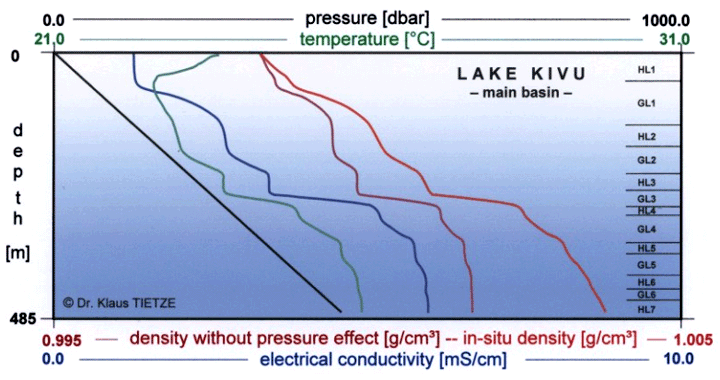
Vertical section of density,
conductivity, temperature and pressure taken together : average of 23 profiles:
K. Tietze 1974 - 75
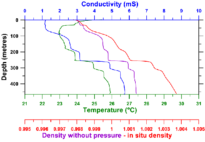
Measurements from February 2002 : to be compared
with the previous figure from 1974
The analysis of the gas content profiles of Lake Kivu indicate that the gas deposits are confined to the interior of the depth contour - 270m - and that a layer favouring the harnessing of the waters of Lake Kivu is to be found at a depth of approximately 350 m. Analysis of water taken from this depth shows that it contains dissolved gases of the order of 2,5Lgas/Leau... This gas is made up of 5/6 carbon dioxide CO2 (2,1 LCO2/Leau), and 1/6 methane CH4 (0,425 LCH4/Leau).
Four field trips to study the physico-chemical makeup of the lake were undertaken in 2002, 2003 and 2004. During these field trips we tried to determine exactly the variations of some parameters having a direct influence on the degassing technique, all the while taking into account the environmental impact of the future gas extraction plant on the lacustrine ecosystem as well as the eventual risk of a gas emanation (of the kind responsible for the explosion at Lake Nyos).
DENSITY CONTOUR OF THE WATER
The density contour of the water plays an essential role in the choice of the optimal process for discharging gas-filled water and the estimation of the risk of a gas explosion. We have therefore concentrated on this area, on the one hand by taking measurements in the lake and on the other by suggesting a model of this phenomenon. The model introduces progressively the parameters which appear to be essential: temperature, content in dissolved ions, content in dissolved gas and hydrostatic pressure. The correspondent calculated contours are assembled in the following figure.
As well as this, we have made a series of measurements of water density obtained either by pumping or by auto-siphon at different depths, from the lake surface down to a depth of 400 m. Density is measured using an Anton Paar densitometer with a resolution of 10-4. Comparable accuracy can be obtained by crossing water samples with measurements of distilled water at a given temperature. Note that the temperature measurements have been obtained with a high quality thermometer with an accuracy of one-thousandth of a degree. The values obtained experimentally are in violet on the figure below.
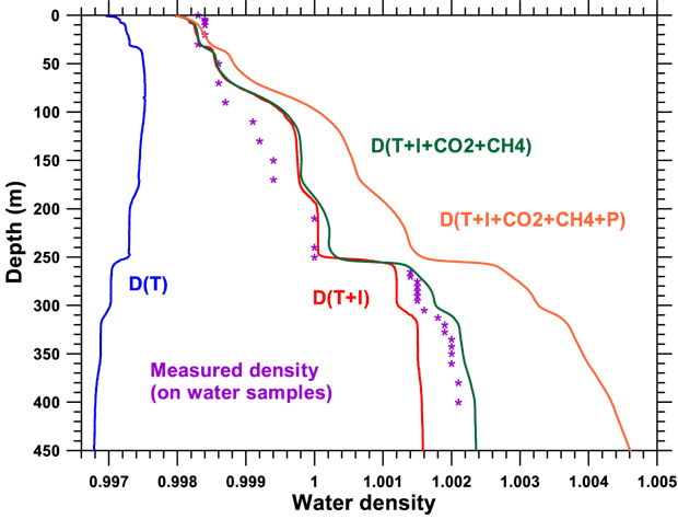
Density contours calculated using physico-chemical parameters measured in the lake. The densities measured directly on water samples are shown by violet stars.
DISSOLVED GAS CONCENTRATION (CH4, CO2) ACCORDING TO DEPTH
Using the experimental column allowed sample collection of water and gas at levels where priming of the auto-siphon mechanisn was possible, that is to say below a depth of 270 metres.
Prelimiary analysis of the CO2 and CH4 content was done in situ, at the exit of the small separator. The figures obtained by means of the Ga2000 infra-red analyser are exact and reproducible.
We have added the respective contents in CO2 and CH4 in the gas taken from different depths between 270 and 400 m to the figure. One can note a small but absolutely crucial diminution in methane content as depth increases. The difference in methane content between the layer at 270 m (27% CH4, 73% CO2) and the layer at 400 m (20.5% CH4, 79.5% CO2) is of 7%.
In the rate of content of gas concentration one can again remark the existence of those homogenous layers mentioned previously (notably the 280 - 300 m layer and the 330 - 355 m layer).
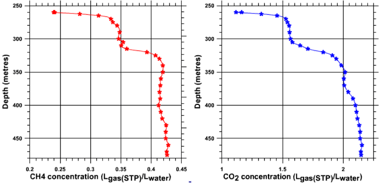
Dissolved gas concentration (CH4, CO2) according to depth (scientific fieldtrip of November 2003)
CONDUCTIVITY MEASUREMENTS
One can notice on the figure below that the dissolved ion content is the most important parameter in determining density variation. At first sight this ion content is linked by a rule of proportionality to electrical conductivity.
Measuring conductivity is relatively easy, either in situ using a CTD (Conductivity, Temperature, Depth) gauge, or in the laboratory on samples taken from different depths.
A vertical contour offering excellent spatial definition was realised using a Seabird CTD SBE39. On this conductivity curve the different homogenous layers of the lake are quite clearly visible, separated by layers of a high gradient of density.
On the figure, for example, the two homogenous layers between 280 and 300 m and 330 and 355 m are apparent. We have also taken a large number of water samples from different depths (either by pumping or by using the auto-siphon technique). The conductivity of these samples has been measured and appears on the figure as blue stars as well as the CTD contour already shown. Note that the two curves are very similar.
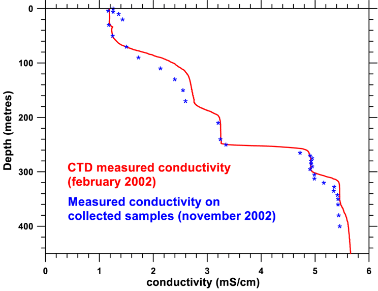
Variation of conductivity curves
: in red is the conductivity obtained using the Seabird CTD SBE39 in January-February
2002 ; the blue points were obtained from water samples taken by pump or by
auto-siphon.
HYDROGEN SULPHIDE CONTENT
Hydrogen sulphide content plays
an extremely important role in a methane extraction programme destined for
energy applications.
Generally, in fact, one considers that natural gas combustion in an engine
cannot take place without rapid wear on mechanical parts (piston rings, cylinder
etc.), if the level of H2S is over 500 ppm.
In the presence of water vapour and at high temperature the hydrogen sulphide is transformed into extremely corrosive sulphuric acid which tends to dangerously shorten the life of an installation's moving parts.
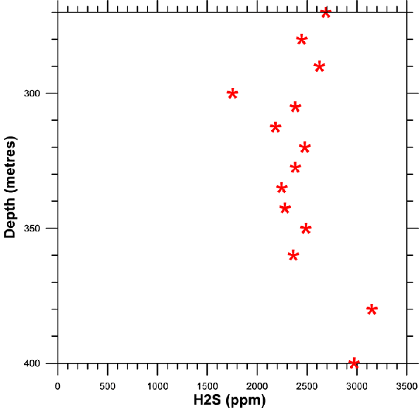
H2S content according to depth. Due to the limit of 200 ppm of our analyser the measurements were carried out on samples diluted 20 times, this explaining the relative dispersion of the results. The average hydrogen sulphide content is around 2500 +/- 500 ppm and does not seem to vary significantly with depth.
MEASUREMENT FIELD TRIP: ECHO contract, January 2002
FINAL REPORT OF THE INTERNATIONAL SCIENTIFIC TEAM (PDF)
Internal reports on our studies of Lake Kivu
Investigations in Lake Kivu (East
Central Africa) after the Nyiragongo Eruption of January 2002, Specific study
of the impact of the sub-water lava inflow on the lake stability. European
Community, ECHO; Final Report of the International Scientific team,
Michel Halbwachs, K. Tietze, A. Lorke, C. Mudaheranwa
The January 2002 eruption of Nyiragongo volcano
(United Republic of Kivu) and related hazards: observations and recommendations.
French Ministry of Foreign Affairs; Final Report of the French-British (Concorde)
scientific team, Paris, March 8, 2002
P. Allard, P. Baxter, M. Halbwachs, J.-C. Komorowski
Rapport sur quelques mesures effectuées
sur la centrale d’extraction de méthane du Cap Rubona les 1er
et 2 Septembre 2002
Michel Halbwachs
Etude expérimentale d’optimisation
d’un système d’extraction du méthane du lac Kivu,
Contrat 2002/035/UE/MS ; Délégation de la Commission Européenne
à Kigali
Maître d’œuvre : Ministère de l’Energie, de
l’Eau et des Ressources Naturelles, République du Rwanda,
Michel Halbwachs - Mars 2003
Exploitation du méthane du lac Kivu,
Projet de station pilote,
Michel Halbwachs, Juin 2003
The exploitation of methane in Lake Kivu, Pilot
station project,
Michel Halbwachs, August 2003
Valorisation du méthane du lac Kivu
– Alimentation de la cimenterie CIMERWA
Michel Halbwachs, Avril 2004
Valorisation du méthane du lac Kivu
– Alimentation de l’usine à thé Pfunda,
Michel Halbwachs, Septembre 2004
The exploitation of Methane in Lake Kivu -
Supplying the brewery Bralirwa,
Michel Halbwachs, Octobre 2004
UN-OCHA report on the scientific expeditions
to Lake Kivu on November 2003 and February 2004: an investigation on physical
and chemical properties of Lake Kivu as a base for gas outburst risk assessment,
M. Schmid, M. Halbwachs, B. Wehrli
FFSA
Federation of the Free States of Africa
Contact
Secretary General
Mangovo NgoyoEmail: [email protected]
www.africafederation.net